PROJECTS:
ANTENNAS:
5m vertical multiband GP antenna
An 80 meter multiturn magnetic loop
TX,RX:
Computer controlled Mobira RC25
Telcom TE-157 - remove the beep
OTHER:
Important links
COMMUNICATE:
Questions, comments? Type them here!
OR email to:

Last update 18.1.2009
General Description about this project:
Year 2004 I found myself studying two different articles about software defined radio and so called 'Tayloe mixer' (also known as Tayloe detector) written by Gerald Youngblood and Dan Tayloe. I realized that this is the future of radios. Studying Software Defined Radios a bit further, it also came quite clear, that this, if something, is a heaven for homebrewer, like me. The basic idea of Software Defined Radio is: "The radio signal is brought as close to the software, with as minimal components as it can be done". My interests here are focused to a IQ based transceiver.
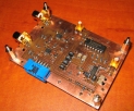
Click the image below to view a series of pictures related to this project
Update 18.1.2009
PowerMate VFO knob:
I've always liked that radio should have a real VFO knob. Untill now, it's been a bit annoying to change the frequency just by clicking with the mouse. PowerMate has become quite popular amongst SDR enthuasists and especially Flex Radio users.
Only small changes had to be done to my hardware controlling software. I recommend this fine product, check it out: PowerMate
Update 10.12.2008
CW key connection:
I've been quite active on learning CW lately and this has actually stolen the time to improve SDR1 or SDR2. KGKSDR supports CW key through COM port, but this is feature that I can't use on my laptop because there's no physical COM ports. So, I thought that I gotta add the connector to my own SDR HW softare, so that I can use the CW key without the physical COM port. Well, to simply put it: succeed. Even took my first overseas QSO, hihi.
QSOs worked with the SDR
45DXCC, 19 of them totally new. Includes Canada, USA, South Korea, Algeria, Mauritius and many more.
Update 25.8.2008
The best configuration: VNC + IP-Sound through VPN
On the last update I mentioned about using a dedicated VOIP solution made by Christopher Svenstedt - SM5VXC, called IP-Sound. This VOIP software has many features that are not supported for example in Skype. The IP-Sound is in use and does it's job really well, I recommend it to everyone building your remote controlled station.
I also compared different remote desktop methods and here's short description of what I found:
Test QSOs were made with WLAN (in same private network with the server) and through a mobile internet connection (around 300kbs).
Update 4.8.2008
SDR TRANSCEIVER AS A REMOTE CONTROLLED STATION
Yesterday evening an important goal was achieved. For the first time, the SDR transceiver was used as a remote controlled station. A good fellow of mine, Kimmo - OH7FDN has been a great help and has shared his knowledge about setting up a VNC (virtual network computing) which enables the easy use of a remote desktop. We used skype as an VOIP application (Voice over IP), but we also did notice that there is much lighter solution available made by Christopher Svenstedt - SM5VXC which is dedicated to this purpose. We will definitely try this later. All the possible processing power should be left for the SDR demodulation/modulation software and so, use the lightest applications there are available.
The setup is physically quite simple. The skype uses laptop's integrated sound card and KGKSDR (demodulation/modulation) uses the SDR dedicated E-MU 0202 USB sound card. The output of the integrated soundcard was connected, with a physical wire, to the mic input of the SDR transceiver and the line output of the SDR transceiver was connected to the input of the laptop's integrated sound card. Two sound cards are in use because the nature of the KGKSDR and because the VAC (virtual audio cable) can't handle ASIO.
The first remote QSO was kept by Kimmo - OH7FDN, with Markus - OH1MN 3.8.2008 around 20 UTC.
Kimmo was physically at the northern part of Finland, while my station is at the west coast Finland, giving a remote distance of around 400km.
Update 26.7.2008
One parameter of the SDR transceiver is now measured: Sensitivity.
The test was done with a rohde swartz radio measuring station. The sensitivity with a 2.1kHz filter was around -130dbm and with 500Hz CW filter few dB more.
This is more than adequate sensitivity for HF since the high atmospheric noise. With this sensitivity and proper antenna, you hear everything there is available from the antenna itself.
Update 14.7.2008
Great news and a WARNING!
WARNING: Don't imagine that you can add parallel port to your computer with these USB to Parallel port adapters. No can do... These add only a printing support, not an port that would appear physically to your software. Also, beware of the Expresscard converters, since many of them also appear as an USB printing support. The Expresscard I mentioned on 27.6.2008 update, didn't work either.
The GREAT news is, that because the struggles mentioned above, I had to make the USB to Parallel converter myself and I though: "what the heck, I'll make it to the same size with the cards inside the rig and stack it over existing cards". I had to do a LOT of rewriting to the software, but it was all worth. Now I can use the SDR with any laptop with enough processing power and USB connectors. No physical COM or Parallel ports are needed.
I will post new pics of the FINAL setup soon.
Update 27.6.2008
Lots of things happend within last month so here's a short list first:
Because newer laptops don't have any COM or LPT ports, I was in the middle of a new challenge. Earlier, I've made the KDKSDR and my SDR HW control software to talk (PTT information) through a physical COM port. Now, with the laptop, I tried several different Virtual COM ports and even bought an USB to Serial converter - none of these worked and I tried really hard, really.
So I started looking ActiveX VB6 Virtual COM applications and found a decent one: VPS AX 6 by Eltima. The evaluation version can create only one COM port or a pair of COM ports (solid 6 and/or 7) and the amount of data is limited to 10kb. It has a pop up window included in the DLL, so when I run it, it gives this "Thank you for evaluating this... ". The point is, these doesn't bother me at all. The limit of 10kb data doesn't limit controlling PTT. I got everything working with the price of this little pop up window.
So, I made an small software that can write/read to Virtual COM port and added it to my SDR HW controller VB6 project. I got rid of the need of physical COM port and can now use the SDR system on my laptop. The PTT in KGKSDR can be controlled with F9 and F10 keys, which I found to be extremely pleasant. No external PTT switch is needed and in my opinion, less is more.
Also, I bought an Expresscard LPT port. I found those to be very difficult to find. There's luckily almost everything on ebay that you can imagine. Unfortunately, I got wrong information and ordered PCMCIA card... Thanks to guys at Finnish ham IRC channel, I was straighten out and told that the card slot is for Expresscard. Thanks guys!
I will add new pics of the WHOLE setup really soon!!!
Update 27.5.2008
Now over 100 QSOs has been made outside Finland, the longest QSO being Mauritius island, with a distance of approximately
9500km. The total amount of QSOs lay somewhere between 200 and 300. If you look back the news on this page, you can see
how long it has been taken to collect 35 DXCCs (sitation today) and 100 QSOs with the SDR. The QSO no. 100 was kept 17.5.2007.
The amount of updates to SDR will now decrease quite much hence the new transverter project, which of course will be a part of the
SDR transceiver, but I will open a dedicated page for it (under oh1gtf.com of course). The transverter will transform the SDR TRX
to a full coverage from HF to 70cm. The 1st plan is to add 6 meters to be able to enjoy the awesome ES and Tropos at the summer time.
Update 30.4.2008
Whohoo :) The E-MU 0202 USB sound card arrived. Short tests were made and the card has proved itself a worth for the payed money.
It's a bit noisy on 192kHz but seem to be as silent on 96kHz as my E-MU 0404 PCI card (which is very silent). I noticed, Immediately
after I opened the box, that it wont fit inside the TRX, but no worries, the box looks awesome and visually fits at the top of my
SDR TRX really fine. So, all good news this time :)
One IMPORTANT thing for you to know: E-MU 0202 doesn't require sample delay on any of the sample rates, so it can
be used on any sample rate with any SDR software. For example my E-MU 0404 PCI card limits the use of different SDR softwares
because the required 4 sample delay on 192kHz and 3 on 96kHz. So far I've been able to use only 48kHz sample delay with 0404,
but now can have anything between 44kHz and 192kHz, nice.
I'm also building a second SDR RX as a test equipment to measure the differencies between the sound cards. This way I can monitor
the TX noise and image rejection of my SDR TRX.
Update 21.4.2008
Using a PCI soundcard makes the transceiver very unportable system. Taking my home PC along the
transceiver every where I go is just unpractical. Maybe not the full solution to this problem, but most
of it, is an USB soundcard. I ordered an E-MU 0202 USB soundcard which should have the exact same
characteristics as my E-MU 0404 PCI card has. I will tear the whole 0202 box apart and see if the
electronics fit inside the transceiver
Now I can put all the necessary softwares on to one CD rom and put my transceiver to work with any
computer in a matter of minutes - even with a laptop.
Update 15.4.2008
Worked 30 DXCC, including South Korea and Canada. 6 of them totally new.
Update 28.3.2008
I've already worked 15 DXCC with the SDR trasceiver. 3 of them totally new to me.
Update 12.3.2008
Added several pictures. Click the image above to see the series of pictures.
Update 11.3.2008
Within two days I've worked 5 DXCC countries with no trouble.
Update 5.3.2008
Latest updates:
1.3.2008, me and Markus, OH1MN headed to our HF club, OH1AA. We had a great evening in the name of sauna, grilled sausage, few beers and
of course, radios. I brought my SDR transceiver and computer with me to test the signal handling capabilities of the receiver section.
We used an 20 meter monoband beam and 80 meter dipole. The bands were crowded because the on-going contest, so it was a good time to test the RX.
Even the strongest stations couldn't produce overloading of the receiver. The RX was more than enough sensitive. Well, it works really well even
with my small multiband GP at home, so why wouldn't it do the same with big antennas, hi.
We took even one QSO (wasn't our purpose then) to Holland with PE2EK, Bram.
Update 28.2.2008
Few things happend since last update:
Pictures will be added soon.
Update 19.2.2008
First overseas QSO taken with the SDR transceiver. The opposite station was a Finnish guy living in Switzerland HB9EDY, Heikki. We had
a nice 10 minute chat. This QSO was my first overseas with fully homebrew station: GP antenna at the backyard, KGKSDR software
and well discussed subject at this page, my SDR transceiver.
One fine feature of the SDR TRX: I was able to record the QSO just by pushing one button. You can listen it by clickin
THIS. The recording is publiced with the persmission of HB9EDY.
Update 15.2.2008
The PA is finished! I decided to settle with 10W output, so the PA is using directly 13.8 Volts. I had a little bit
instability problems in the beginning: The input balun's core didn't handle much power and it started to saturate at
really low power levels. Also an 3db attenuator was added between the 1W amp and PA to improve the wideband matching.
Now the whole amp chain is really stable providing solid 10W output from 160m to 10m. Check the pic I added (the picture
link above).
Next task is to make the lowpass filter board.
Update 8.2.2008
I've been designing an 10W amp with PCB cad the last few days. Today I'm gonna transfer the mask to the board
and remove the extra copper with ferrichloride. Have I told you that I use heat/Ink transfer method these days?
The design is quite straight forward, based on the "Broadband HF amplifier" -design that can be found from later ARRL handbooks.
It uses cheap IRF510 mosfets and provides an output in the range of 10W-70W depending of used voltage and band.
Using 28 Volts, you achieve over 40W on all bands from 160m through 10m, but with 13.8 Volts you can achieve 10W reasonable output.
Wanna catch me up on HF using this transceiver? Just drop me an email and well schedule a QSO!
Pictures will follow soon.
Update 30.1.2008
Great news!
The transceiver is now a 1W all mode HF. Added few pictures more, check out the picture link above.
First actual QSO was made with OH1MN on 20 meters. Markus was kind to give me 59, which was a real report.
You can listen the audio that Markus recorder on his side by clicking THIS link.
According to Markus, he had quite huge QRM at the time, so this explains the hiss on the background.
Update 6.1.2008
The latest progress:
The DDS reference oscillator has output of 425MHz. It is based on 106.25MHz "can" oscillator and I'm
picking out the 4th harmonic with strip line filters (one at the collector of the 1st transistor stage).
This oscillator seems to have quite round output, so it doesn't create much odd harmonics
(this is the conclusion we came with my friend Timo - OH1AZL). So, it is easier to pick out some of the
even harmonics, in this case the fourth one.
Update 18.12.2007
The transmitter board is now almost complete. I should receive the required last few components today.
Wanna take QSO soon? Hi.
As usually, I will add pictures immediately the board is finished and proven that it's working, hi.
IMPORTANT NOTICE: I've decided not to share the schematics anymore. What I heard from Yu1LM (who is also grazy lover of SDR stuff)
through a yahoo SDR group, is that his desings were used by someone, commercially!!! I've always thought that it's not necessarily wise
to share the schematics, even though it is informative and interesting for the readers. My idea originally was to inpsire the readers
and not to offer readily chewed gum. So this news from YU1LM brought me to this decision. Sorry about that, but I will still give quite
accurate details if not something unigue is invented, hi.
Update 10.12.2007
Been working with Visual Basic and actually have now software that is fully functional. It controls the DDS (frequency),
all the filters (LPF & BPF) and PTT. Just finishing graphical interface to make it look a little bit cooler.
a HUGE thanks goes to Andreas DL5MGD, who's DDS control software is available at his homepages. This helped me alot. Andreas
has also been a great help for sesolving one DDS controlling problem that I've been struggling with. Thank you Andreas!
As usually, more pics coming soon. Propably about the software and the final setup I'm using.
Update 6.12.2007
Update 4.12.2007
AWESOME NEWS! The DDS works great! The SDR project is now full HF RX.
Next step is to finalize the TX design and start making the board itself.
Many pics and few audio samples will be added soon.
Update 2.12.2007
Update 25.11.2007
The 425MHz reference oscillator works! Also the controller board works! I'm only missing few SMD capacitors and
resistors from the DDS board. Will add more images when the boards are fully assembled.
I added one pic to the SDR image series. I'm very pleased with the M0KGK SDR software. Thank you Duncan for your great work and efforts!!!
Update 05.11.2007
The 425MHz reference oscillator and DDS boards are assembled. I'm designing a kind of controller board, which
has connectors for each unit (BPF board, DDS board, TX, RX and so on) to carry needed supply voltages and
information like tx/rx-enable and band data (for BPF and LPF boards).
As usually, pictures are coming soon!
Update 25.10.2007
Find out that there is no need for chokes between the QSD and preamps. They add noise over 10db. Taking them off
I was able to increase sensitivity 10db - as the noise went down exactly the same amount of db. I also didn't find
any need for limiting preamp's bandwidth as much as I did, so after quick calculations, I chose 100pF capacitors to be
placed to the feedback, instead of 4.7nF. This improves the phase balance between the channels on higher sampling frequencies.
Added a picture of WINRAD screenshot. Open the series of pictures from the picture -link above and have a look!
IMPORTANT Update 21.10.2007!!!
I wasn't able to get decent results by using 3253 switches. The problem I had was with linearity, when moving
further away from the zero beat. This is probably due the internal decoder driving the switches and causing unbalances.
I also got tired of LT1115 chip's oscillation problems: I found that this chip to be really unstable. You won't necessarily
notice any oscillation at the first place, but checking the output with scope will reveal unpleasant truth. Well at least,
this was the problem I was experiencing.
So, a came up with a new design which has 74LV4066
as a detector, CD74AC74 as a quadrature generator and OPA228 (3nV/SQRT(Hz) operational amplifiers as preamps.
I also found, that separating RX and TX to two different boards makes the design and testing more flexible.
Look the pictures in the series above to see new schematic and how the finished RX board looks like. The results are big
improvement compared to the previous design, even though the 74LV4066 has higher on resistance compared to 325X -series.
I can have a way better image rejection (50-60db) over the entire visible 48kHz spectrum. I haven't tested with 96kHz,
but it seems to work at the edges of the 48kHz BW and so would do just fine and even better, on 96kHz.
I chose 74LV4066 because it has quite homogeneous switches and faster switching time compared to the 74HC4066.
I also added few pictures of the finished bandpass filter board. I had the luxury to borrow my friends
MiniVNA (vector network analyzer) to tune the filters in. Thanks Jouni, OH1CO.
Update 21.6.2007
Enclosure finished. DDS board under construction.
Update 2.5.2007
Making the enclosure for the project. There is so much stuff already, that it cant be run just
on the table, hi.
Update 12.3.2007
Got Flex Radio and Digipan softwares working together with VAC (Virtual Audio Cable). I have received PSK transmissions
on 80 meters, from all over the world, with nothing else than few meters of wire inside the shack. I'm starting to design the
DDS board. Also bandpass filter board is under construction now.
More pics coming soon.
Update 4.3.2007
Lots of stuff have happened. I've been really busy with the SDR radio. Here's the latest news:
I had LOT of oscillation problems with the LT1115 high speed, low noise opamps. Really much care should be given to
these opamps if using them! I finally got the oscillations fixed (at least I think so) and the opamps seem to be stable.
I had few problems with tricky software routings though. I have ASIO card (192kHz-24bit) which makes things a little bit more
difficult and much study has to be done to learn to use the manufacturer's software.
The transmitter section worked immediately! I measured 2Vpp over a 47 ohm resistor, which gives a calculated power of about 10mW.
Really awesome, with nothing else than the exciter itself. Really good power to drive few watt amp. Can you see the excitement??? :)
Here is few clips taken with the receiver:
Update 28.11.2006
QSD/QSE PCB desing finished! Added a picture of the QSD/QSE PCB board.
Update 25.10.2006
The drawing of the QSD/QSE circuit board with PCB CAD has begun. When the design is finished with the QSD/QSE board, I will move to the DDS
(direct digital synthesis) board. More pictures coming soon.
Update 10.10.2006
Bought all the necessary components like: bunch on amidon iron powder toroids, AD9954 DDS chip, FST3253 mux chips etc. This project will begin
soon. I will keep you updated, including pictures.
Beginning
This is the biggest project I've ever had so far. I have already build a bunch of receivers based on the QSD
(quadrature sampling detector) also known as Tayloe detector. They've worked really well! I also have experience of building
QSE exciter (quadrature sample exciter) transmitter for 80 meters and it also proved itself to be a worth of building.